LFS-1 系列流量测量系统
LFS-1 系列流量测量系统简单介绍
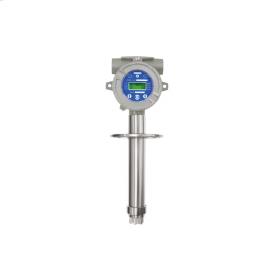
Meriam Laminar Flow Elements (LFEs) are excellent for measuring low gas flow rates from 0.2 SCCM up to 2250 SCFM. They are inherently accurate and repeatable and are calibrated traceable to NIST in our ISO 17025 certified Flow Lab. Flow turndown is 20:1 or better and the differential pressure generated is nearly linear to flow. This combination makes an LFE a great choice for gas flow measurement and flow control applications. Performance Standard LFE calibration accuracy is ± 0.72% of Reading (not % of Full Scale) traceable to the National Institute of Standards and Technology (NIST). Rigid construction and lack of any moving parts make the LFE calibration stable. Only physical damage or particulate deposition in the element will cause a calibration shift. Utility LFEs can be used to measure flow rate for a variety of gases and applications. Standard models are available to measure as little as 0.2 SCCM (5.9 E-06 SCFM) to as much as 2250 SCFM of air flow at standard conditions. Custom models for up to 15,000 SCFM of air are available. Stainless steel or aluminum materials make LFEs compatible with most gases. Flow rate of gas mixtures can also be measured when the percentages of component gases and mixture properties are known. The LFE Matrix The LFE matrix can be made from individual SS tubes or windings of SS foil. These tubes are long enough, relative to their inside diameter, to cause laminar flow to occur inside each tube. The result is a near linear relationship between DP and flow rate. The DP generated across the matrix responds very quickly to changes in flow. All DP is permanent pressure loss to the system but LFEs are sized to produce no greater than 8” water column at maximum flowing conditions. Individual tube diameters are very small so flowing gases need to be clean and dry to preserve the calibration. Filtered inlet versions of most LFE models are available to keep the matrix clean and the calibration constant. Calibration and Accuracy
LFS-1 系列流量测量系统的详细介绍
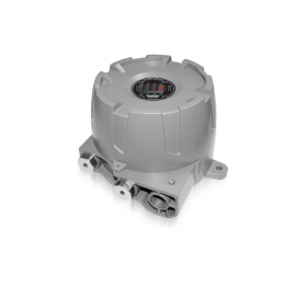
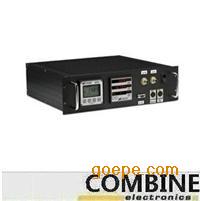
LFS-1 系列流量测量系统LFS-1The LFS-1 Flow Measurement System for Meriam LFEs takes advantage of the wide flow turndown and the percent of Reading precision of the LFE, as well as Meriam’s calibration expertise, to provide a superior gas flow measurement solution. The integral flow computer makes real time corrections for changes in differential pressure, static pressure, temperature and relative humidity to provide the most accurate results possible. Calibration coefficients for up to five (5) LFEs can be stored in memory and called up for later use with a push of a button. For control or data transmission purposes, the LFS-1 Flow Measurement System has both analog and digital outputs. 4–20 mA and 0–10 volts analog output options are ideal for control and recording functions. RS-232 and RS-485 digital communications are standard.
Special application requirements can often be accommodated by the LFS. For example, simultaneous flow measurement of two LFEs can be made and the summation of the two flows calculated and displayed. Or, for testing over a wide range for flow, the LFS can be set up to automatically switch from one LFE to an LFE of a different flow capacity as flow rate increases to a predetermined set point.
Meriam’s LFS-1 provides standard system accuracy of ± 1.0% of Reading over a 10:1 flow turndown and ± 1.1% over 20:1 turndown. Calibration of the LFE and LFS-1 as a system makes this possible. Meriam can offer LFS accuracy as low as 0.60% of Reading over a 10:1 flow turndown by using better calibration standards. All LFS packages include complete instrumentation, system calibration and NIST traceable documentation. LFEs and systems cover gas flow ranges from 0.2 SCCM to 15,000 SCFM.
To provide the accurate answers you need in the shortest amount of time, please provide us with the following ordering data:
1. Model number.
2. Flowing gas data;
a. Flow rate in desired units.
b. Base conditions.
i. Pressure
ii. Temperature
c. Flowing conditions
i. Pressure
ii. Temperature
iii. Viscosity at flowing temperature.
d. Differential at maximum flow.
e. Specific gravity, if other than air.
f. Flowing gas, if other than air.
3. Readout instrument.
4. Description of installation configuration.
5. Line size.
6. Line Material.
7. Accuracy required
 扫一扫,手机浏览
 ¥面议
¥面议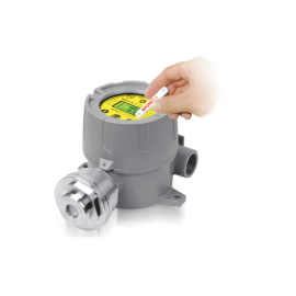 ¥面议
¥面议